AL-811H
Repair and Modification
This page has information on how to check the AL-811H amplifier for problems and how to make these repairs. This page has also been created with the help of W8JI.
The AL-811H went through some changes in 2011 so If you have an AL-811H that was built before 2011 you might want to do the following mod. I have done the mod and The amplifier is working great! 700 watts pep output on most all bands. The repair to the rear band switch and realignment is also included as well as D16 which appears to be a common problem in these amps.
Warning!!! This mod will require you taking the cover off of the amplifier. There is lethal voltage on the inside of the unit. If you are not experienced with electronics, do not attempt this mod! The very high voltage can kill you!!! All voltage must be drained from the unit before removing the cover. Unplug the power cord and let the power dissipate for at least one hour with, all switches in the up position except the switch on the left; leave it set to HV and make sure the meter is at zero, before removing the cover.
You have been warned!
NOTE: Read each step fully before proceeding with that step!!!
This is an important modification to the AL811H. This mod removes the grid resistors and bypass capacitors, and directly grounds the grids.
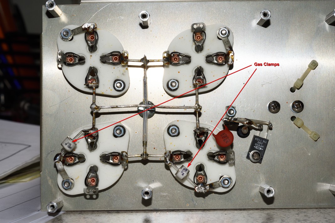
In addition two gas voltage clamps, GT1 and GT2, are added. These are 125-150 volt clamps. These clamps are available from orders@ctrengineeringinc.com.
This mod prevents:
1.) relay damage
2.) exciter damage
3.) grid resistor failure
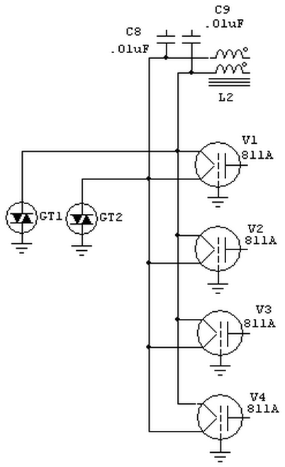
New schematic
Since the AL811H amplifier was initially designed, vacuum tube construction has become less reliable. Tubes these days have much more tendency to arc from anode to grid due to the poor assembly process of Chinese manufacturers.
This modification improves reliability of the amplifier by directly grounding the grids. Amplifiers produced after early in year of 2011 have this modification. If your amplifier has grid resistors mounted on terminal strips near the tubes and balun, it could use this mod.
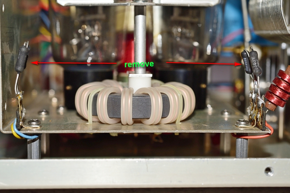
Arrows point to grid resistors
1. ) The first thing to do before removing the cover, is to unplug the amp and let the power bleed down from the amp. Make sure all switches are in the up position except the switch on the left; leave it set to HV. This will allow the power to run down to zero through the bleed resistors. This can take awhile and you should see no voltage on the HV meter scale (left meter).
2.) Once voltage is at zero and the unit has set for a while, it should be safe to remove the cover. Do not touch anything inside the unit until, you have checked with a voltage meter, that no voltage is present. Check the main capacitors with the positive meter probe and the negative probe attached to ground. Make very sure no voltage is present inside the amplifier.
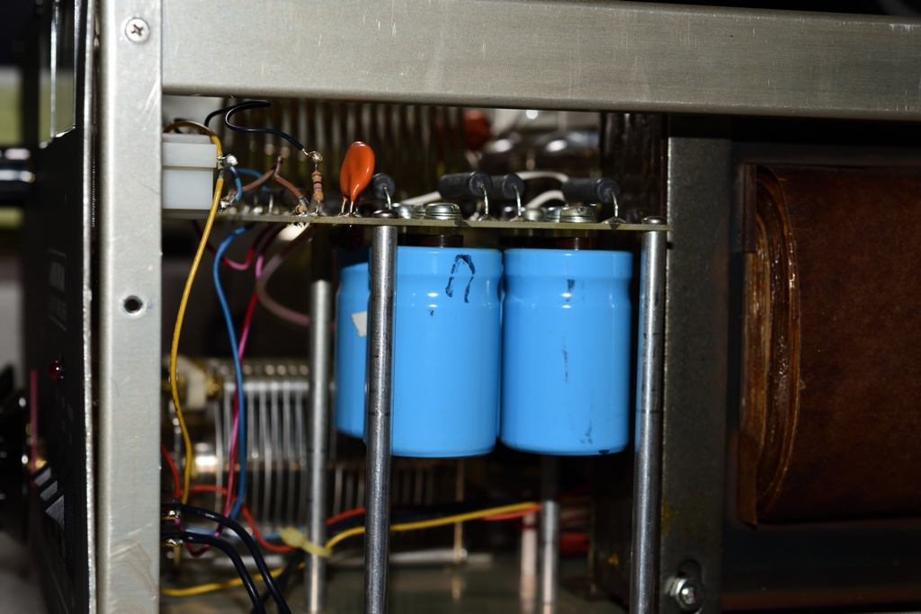
The Main capacitors (above) are either dark blue or light blue (4) 270 MFD 450VDC.
3.) Remove the side bars from both sides of the amp and remove the tubes. A little twisting motion while pulling up, will help get the caps off the tubes. If the contacts inside the caps are a mess, clean them if you can or replace them.
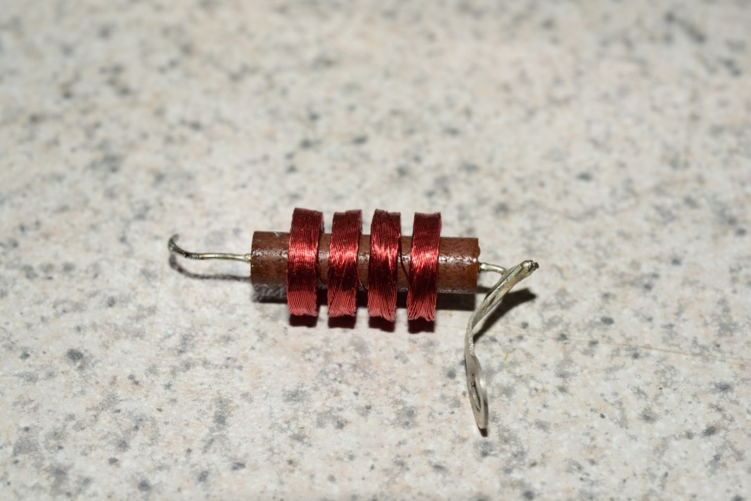
4.) Check the grid resistors for voltage and if no voltage is present remove them from the mounting plate and replace the screws that held them in place. Take great care with the resistors on the right side and do not damage the 4-PI plate choke that sits above the resistors. Remove the choke from the resistor terminal. Be careful not to knick or cut the fine insulated wire in the choke winding! Put the choke in a place where it will not get damaged! Let the resistors hang loose from the wire they are attached to.
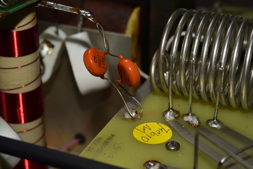
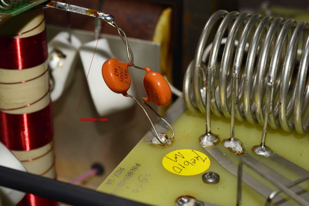
5.) Unsolder the two orange 7.5KV blocking capacitors from the strap coming from under the parasitic PCB that sits in the middle of the tubes and move the capacitors out o the way.
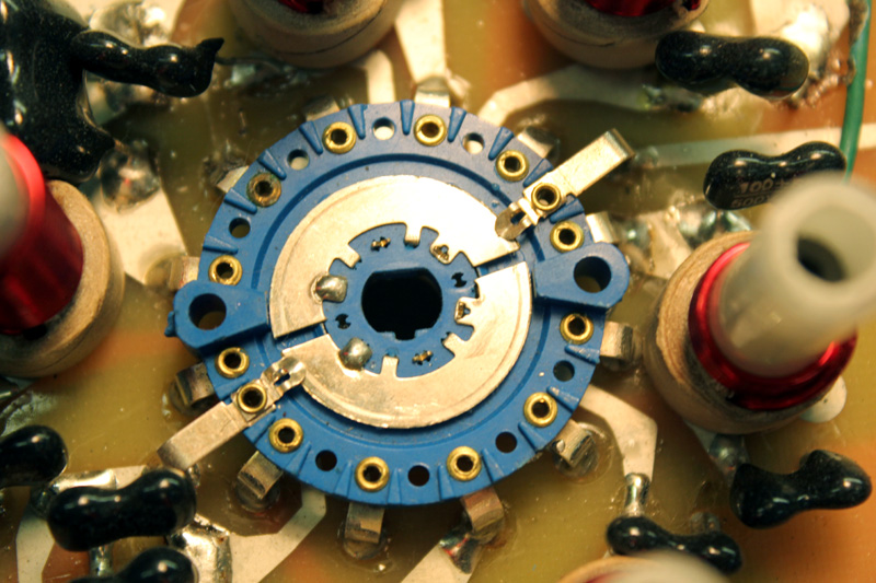
6.) Set the band switch on the front of the amp to 160 meters then loosen the FRONT set screw only, on the switch coupler. You will need a 2.5mm allen wrench or similar tool to loosen the set screw.
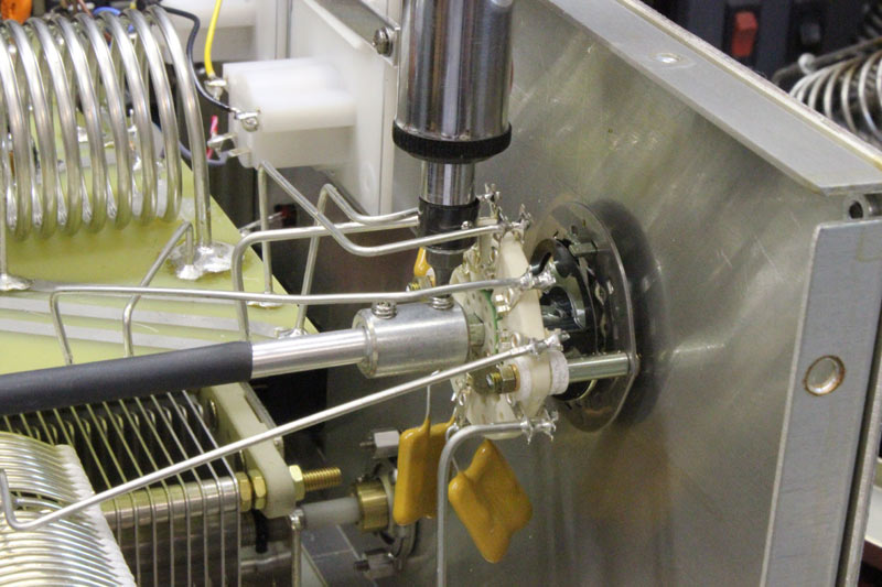
7.) Remove the three screws at the bottom of the back plate and hold the back plate in place. With one hand on the switch coupler and the other on the back plate, gradually move the back plate rear-ward and slide the switch coupler away from the front switch then, out of the back switch while trying not to turn the back switch. Care should be taken before removing the coupler from the back switch so it does not get damaged!!! It is a real pain to replace the back switch if it gets damaged!!!
8.) unsolder the capacitors going to the parasitic board.
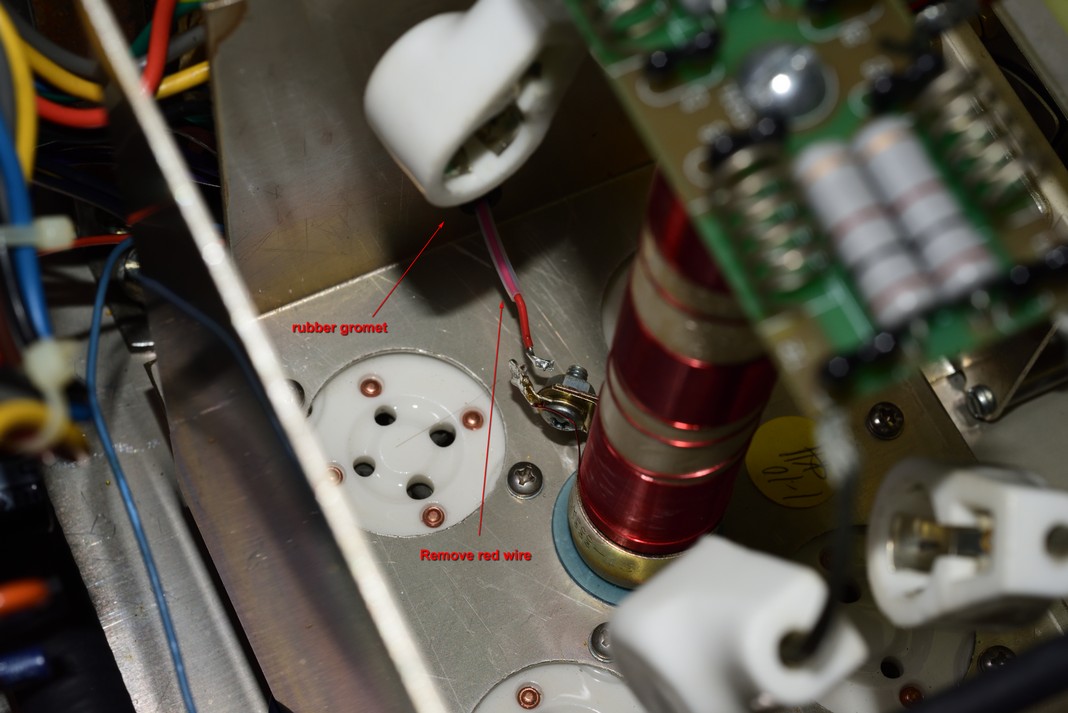
7.) Unsolder the red wire that attaches to the bottom of the Plate choke.
8.) lift the amplifier up onto the side which, has the transformer so, the transformer is on the bench or table side.
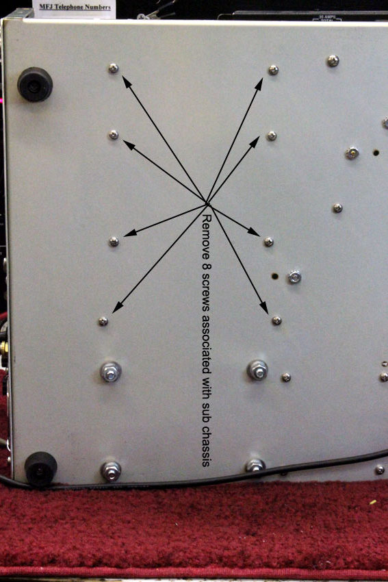
9.) Remove the eight screws that hold the tube sockets and plate. Start at the bottom and work your way up. When you get to the last two screws loosen them while holding on to the sub-assembly. While removing the last two screws, hold on to the sub-assembly to make sure the sub-assembly dose not fall out. You can now lay the amplifier back on to it's rubber feet (right side up).
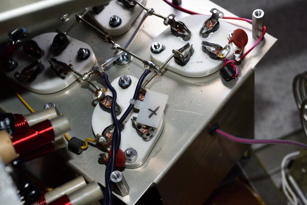
10.) Rotate the plate upside down and locate the two black wires that attach to the tube socket jumpers. Mark one of the wires as shown in the photo below with a wire zip tie then, unsolder both wires from the jumpers. Remove the red wire that you took off the plate choke and pull it out of the rubber grommet.
13.) Remove the subassembly from the amplifier and place the amplifier out of the way. Clear the bench!
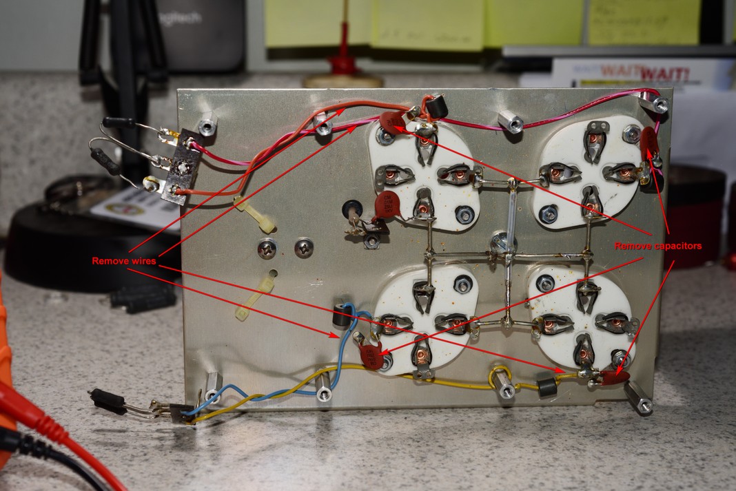
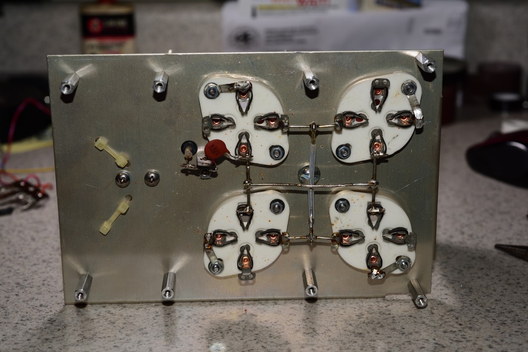
14,) The photo below shows the bottom of the sub-assembly. Next, remove all other wires that were attached to the grid resistors and the bypass capacitors from the grounding straps. Solder all tube grid points (pin #3) to the grounding straps. You will have to loosen the nut and bolt that holds the grounding strap in place to move it. Once the grounding strap is in place retighten the nut and bolt but, DO NOT OVER-TIGHTEN! Over tightening the socket mounting screw can brake the ceramic socket!!!
Your sub-assembly should look like the photo below, when finished.
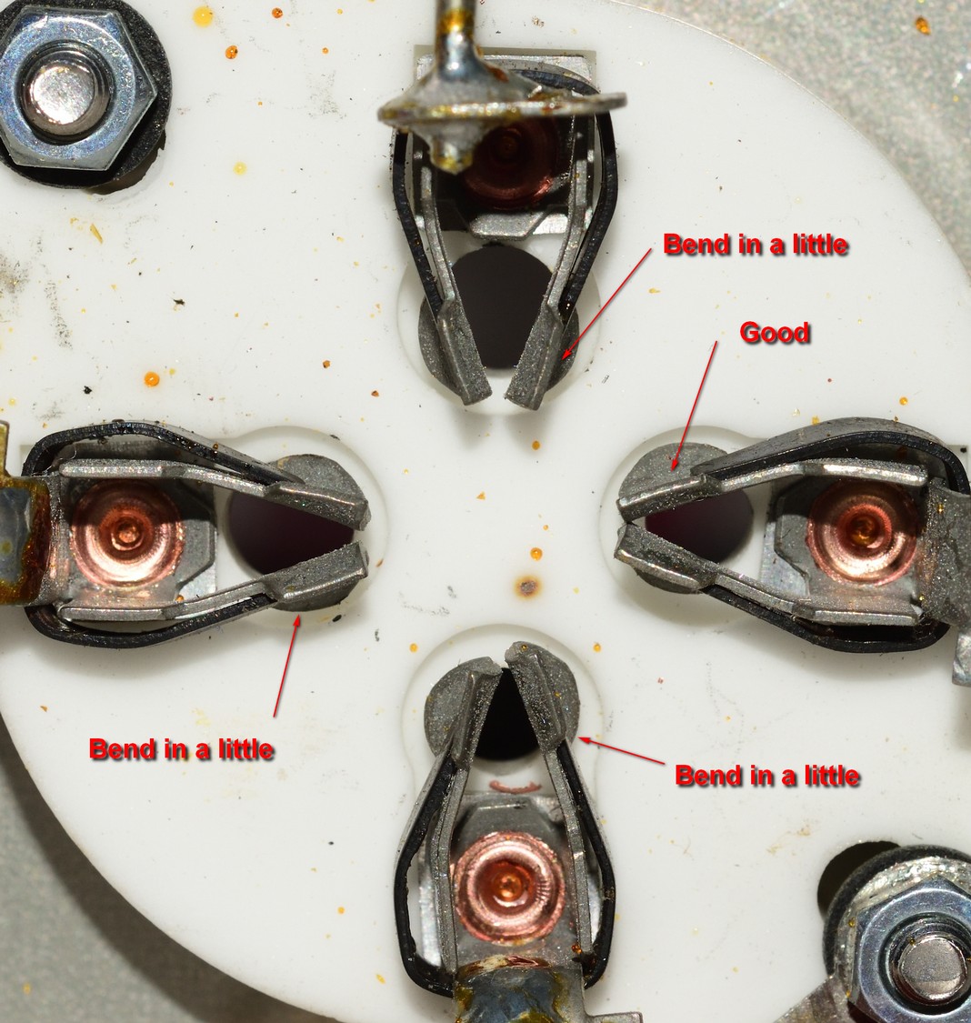
15.) If the tube socket connectors are not straight, you could have a problem getting a tube to insert without the tube suddenly, slamming down into the socket. Check that all socket connectors are straight. When a tube is inserted into the socket; the connectors should hold on to the pins of the tube snugly. You do not want to have any socket connectors that will be loose on a pin. The connectors are spring loaded on the outside of the connector to help put a squeeze on the tube pins. Just check to see that they are straight, together and line up in the center of each post hole.
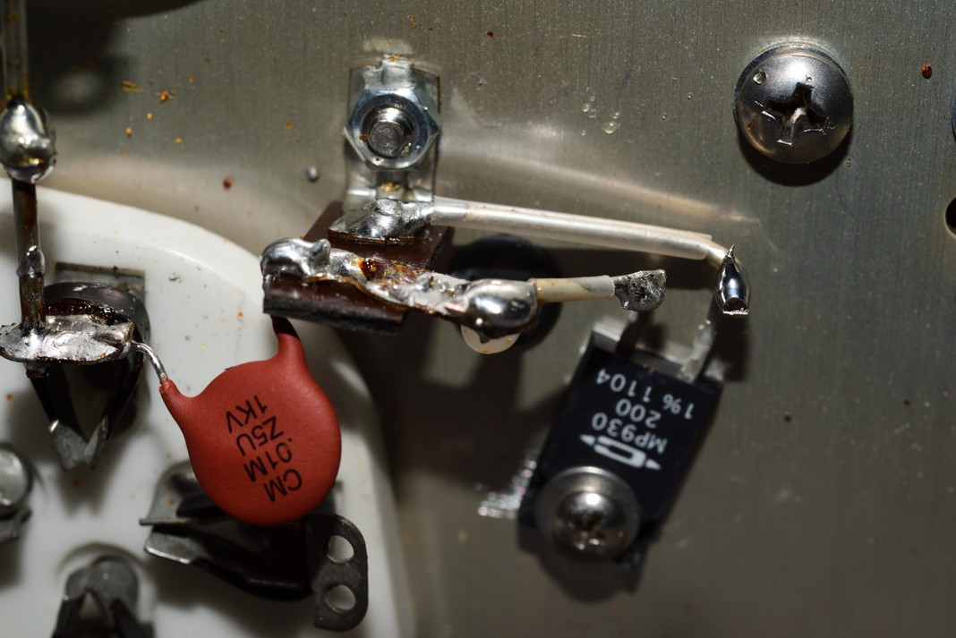
16.) Drill the plate and make sure the are no metal shavings left behind. Attach the 200 ohm resistor and solder it in place as shown in the photo below with one leg to ground and the other leg to the remaining capacitor.
17.) Solder in both gas clamps as shown in the photo below. Now place the plate assembly upright on the bench top and check the clearance. There should be no components touching the bench top except, the plate standoffs.
18.) Now add the two black wires back to the socket jumpers with the tagged wire to the top jumper and the other black wire to the bottom jumper, as they were before they were removed.
19.) Put the red wire back through the rubber grommet and resolder it to the plate choke.
20.) Reinstall the plate sub-assembly into the amplifier and fasten in place with the screws into the standoffs.
21.) Resolder the two 7.5kv capacitors to the strap connecting the parasitic board.
22.) Reinstall the 4-PI plate choke that was connected to the right side grid resistors.
22.) Now is a good time to check the alignment of the rear band switch. While in the 160 meter position, the commutator gaps, align with the ten meter contact eyelets.
This means as the switch rotates to higher bands, the gap progresses CW (clockwise) and aligns with 15, 20, 40, and 80, and 160. If the rear band switch is not currently in the position shown below, you will need to realign it before reinstalling the switch coupler. If it is not in alignment, loosen the rear couple set screw and carefully place the rear of the coupler into the rear switch. Attach the front of the coupler to the front band switch and tighten the front set screw. Now loosen the rear set screw and turn the rear coupler shaft until, the rear band switch is in proper alignment and the tighten the rear set screw. Now loosen the front set screw and replace the three screws that hold on the back plate. Once the back plate is on tighten the front set screw on the switch coupler. More information can be found here.
23.) Reinstall the side rails.
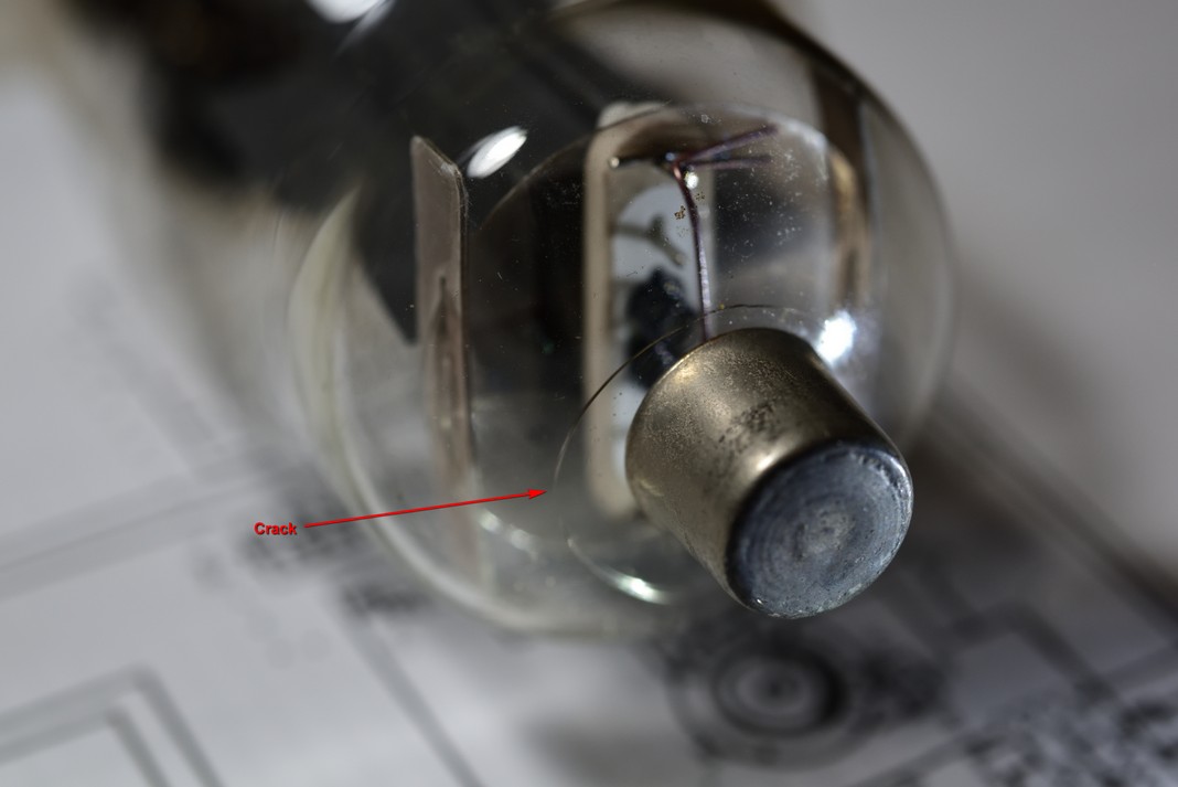
24.) Reinstall the tubes or install new tubes. I purchased new tubes and installed them because, when I took the old ones out, I found one was cracked and they were also mismatched tubes from different suppliers. See the crack in the photo below? Be careful inserting the tubes into the sockets. Rock them very slightly to insert them but, take care they do not slam down into the socket then, put on the tube caps with a slight twisting motion. Take care not to crack the top of the tube with the cap, as the one pictured below.
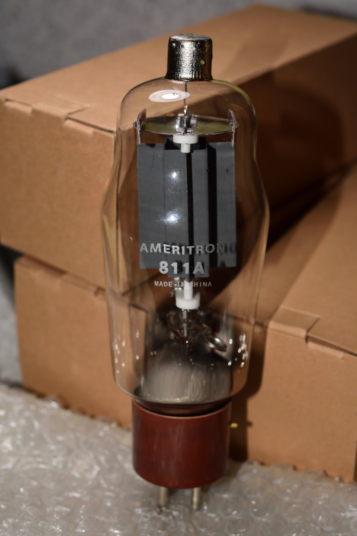
The new tubes that went into the amp came from Ameritron.
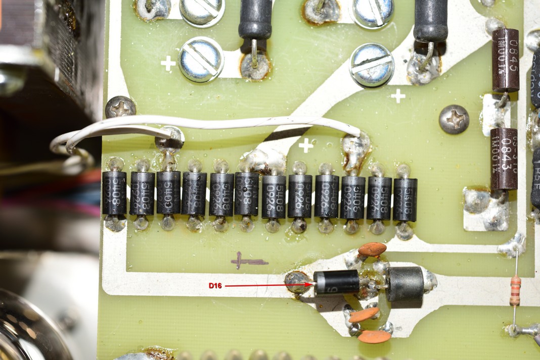
25.) I checked the Diode #D16 and found it to be bad and replaced it while I was in the unit. If the Diode is bad, it will have continuity in both directions of the diode. Left one leg of the diode to check it.
At this point, I was ready to put the cover back on and fire it up to test it. I had already checked most all other diodes and found them to be in woking order. I did replace the main capacitors after checking them. I found a very wide variance of capacitance on all four Capacitors so, since they were already 10 years old, new ones went in. I ordered 4 capacitors from Ameritron and they were much closer to 270 MFD than the old ones so, in they went. I did find out later on that ctrengineeringinc.com has them and they have a tighter tolerance. Next time!
I hooked up the amplifier and fired it up. so, far so good! 1700 Volts plate! I let it sit idle for about 15 min and rechecked the plate voltage and was still at 1700 Volts. I put the meter switch in the IP position and both meters were at zero. So, I started to tune it up using W8JI's tuning procedure on 20 meters and all went well, on the dummy load. The tune up procedure can also be found here.